3D-kousai-opus5: The Office Floor Plan That Proves Itself in Code
A bespoke Three.js digital twin that turns one corporate floor into a unit-testable source of truth, with synchronized 2D and 3D views, compliance checks, and a single-file build.
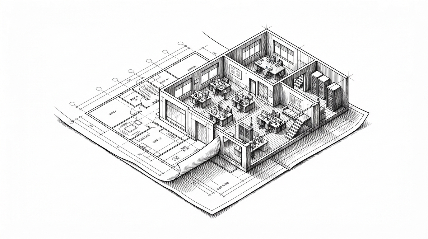
- 3D-kousai-opus5 treats an office floor as verifiable data, not as a static model file.
- The same plan structure drives the 2D blueprint, the 3D scene, and the compliance checks, which prevents drift between views.
- Its biggest product advantage is portability, because the whole experience ships as a single HTML file.
- The project is closer to an auditable facility tool than a generic 3D viewer or a heavyweight BIM workflow.
Why this floor plan matters
Most 3D office viewers stop at presentation. This one tries to prove something: that a specific corporate floor, in a specific building, can be represented as structured code and checked against the numbers that matter. The result is less like a render stack and more like an auditable facility artifact.
That matters because office space is never just visual. It has areas, exits, fire shutters, walking distances, and occupancy constraints. If the model can compute those facts from the same source that draws the walls, then the floor plan stops being a picture and starts behaving like a system of record.
One source of truth, two views
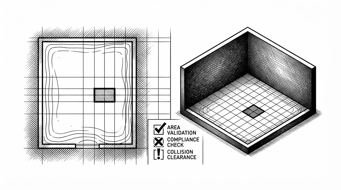
The most important design choice in the repo is also the simplest: one data structure feeds multiple views. The floor plan is not authored twice. Instead, a shared `plan.js` source describes rooms as rectangles, dimensions, and metadata, then other parts of the app project that same structure into a 2D plan and a 3D environment.
That cuts the biggest source of drift in spatial software. A blueprint can’t quietly disagree with the walkthrough if both are generated from the same room definitions. In this repo, synchronization is not a promise. It is a consequence of how the code is organized.
Architecture as data, not as export
The repository does not lean on a heavy exported mesh file. Instead, it uses modern JavaScript modules to describe the building in geometric terms, then generates the scene procedurally. Rooms are defined with coordinates, the building shell is assembled from those definitions, and validation scripts can calculate whether the totals line up with the official floor area.
// Conceptual shape of the model
const room = {
  name: 'Room A',
  r: [x0, y0, x1, y1],
  confidence: 'fact' // or derived, or design
}

const area = (room.r[2] - room.r[0]) * (room.r[3] - room.r[1])
The confidence labels matter as much as the geometry. Marking a value as fact, derived, or design creates an honesty layer that most visualization tools skip. That distinction tells the reader which parts are grounded in record, which are computed, and which are assumptions made for the model.
How the scene is assembled
The model layer turns the room data into visible architecture. Partitions become walls. The shell wraps the floor. Furniture and people are instantiated from repeated patterns rather than hand-modeled one by one. That keeps the system lightweight, and it also makes the scene feel engineered rather than imported.
One small utility does an outsized amount of work here: `M()`, which converts millimeters into meters for Three.js. That is a tiny bridge between architectural convention and rendering convention, but it is exactly the kind of bridge that keeps a bespoke tool coherent. The code is not trying to be a general CAD platform. It is trying to be exact about one place.
Performance also matters. The repo uses `InstancedMesh` for repeated workers, which is the right move when the scene needs to suggest occupancy without paying a draw-call tax for every figure. The visual result is density. The engineering result is that the floor can still load and move smoothly.
Three ways to move through one building
| Dimension | 3D-kousai-opus5 | Heavy BIM workflow | Generic web viewer |
|---|---|---|---|
| Source of truth | Structured JS data drives 2D, 3D, and checks | Rich model files and authored views | Imported assets often split across tools |
| Portability | Single HTML file | Desktop app, licenses, project files | Usually app plus hosting stack |
| Compliance | Built into the model and scripts | Often managed in separate reports | Usually external or manual |
| Sync risk | Low, because views share data | Moderate, because multiple representations exist | High, because assets are often reused loosely |
| Best use case | One floor, one organization, one audit trail | Large building programs and collaboration | Fast presentation or lightweight walkthroughs |
The viewer is built around three modes. orbit gives you a conventional 3D inspection camera. plan flattens the space into a readable orthographic view. walk turns the floor into a first-person path with collision checks so you cannot drift through walls. The same geometry is doing all three jobs, which is why the tool feels like inspection software instead of a one-off demo.
That collision layer matters conceptually. Once a user can move through the building, the model is no longer decorative. It becomes a navigable environment with rules. In other words, the visualization starts enforcing the reality it describes.
What compliance becomes when it is visible
The compliance layer is where the article’s thesis turns practical. The repo calculates smoke zones, fire shutter placement, walking distances, and illuminance from the same building data used to draw the floor. That means a rule can be inspected in context instead of buried in a separate document.
This is a subtle but powerful shift. Most facility workflows keep geometry and compliance apart, then ask a human to reconcile them. Here, compliance is embedded in the model itself. If the layout changes, the checks can change with it, which makes the tool feel less like a drawing surface and more like an operational control.
Why this beats heavyweight BIM for this use case
This is not a universal BIM replacement, and it should not pretend to be one. BIM platforms are built for multi-discipline coordination, long project lifecycles, and complex authoring workflows. 3D-kousai-opus5 is sharper than that for one narrow job: documenting and inspecting a single office floor in a way that is easy to distribute and hard to misread.
| Question | 3D-kousai-opus5 answer | Traditional BIM answer |
|---|---|---|
| How is the floor defined? | As simple structured data that can be tested | As a rich authored model with many layers |
| How is it shared? | As one self-contained HTML file | As project files, apps, or hosted services |
| How easy is it to audit? | Very, because checks sit beside the geometry | Strong, but often through separate tooling |
| How much overhead is there? | Low | High |
| How much flexibility is there? | Focused, but limited to this kind of problem | Broader, but heavier to operate |
That tradeoff is the point. For one floor, one company, and one repeatable workflow, the leaner tool can be the better tool. It is not trying to satisfy every stakeholder in the construction ecosystem. It is trying to be trustworthy, portable, and fast to inspect.
The portability trick
The most corporate part of the project may be the most elegant part: it ships as a single HTML file. No app install. No server dependency. No special viewer. That makes it easier to email, archive, mirror internally, or open in constrained environments where a full platform would be awkward or impossible.
That constraint changes the product shape. A facility manager does not need a stack. They need something that opens, renders, and proves its numbers. This repo treats portability as part of correctness, which is why the whole system feels unusually disciplined for a 3D web project.